mobile

Adding database support for local Azure Mobile App with Node.js

Microsoft Azure Mobile Apps have support for node.js. You can easily clone the app backend to your local machine and test / debug your application there instead of deploying it to Azure on each change. Database support for your local copy can be achieved using a special file called azureMobile.js in your projects root folder as you can read in the holy bible of Azure Mobile App with Node.js.

As you can see in the data part of the configuration it says “mssql” as the desired platform. I don’t know if there is any support for other platforms, but looking in the documentation and the code I could not find any.

Unfortunately as a mobile developer participating in many iOS related projects I work on Mac OS X which lacks support for MS-SQL Server. So why not use Microsoft Azure itself?  Create a new SQL database (or use your existing one if you like), add your credentials like shown in the Gist, start your local app aaaaaand ….. your app will crash silently.

An Azure Database Server instance allow only local connections by default. You can add an exception for your development machine by selecting “All ressources” -> Your SQL Server -> “Firewall” -> And “Add Client IP” in the Azure Portal.

This is an adequate option for an app still in development, but please don’t use this in production mode. You should consider adding a second SQL Server instance for that case. One last advice: Don’t add azureMobile.js to your versioning system.

Firewall settings for an Azure SQL Database.

Firewall settings for an Azure SQL Database.

Summary:

  1. Create azureMobile.js in your projects root folder
  2. Create a second database-(server) for development in Azure and add the credentials to your azureMobile.js
  3. Adjust the servers firewall settings to allow access for your local development machine
  4.  Make sure azureMobile.js is ignored by your versioning system (e.g. add it to .gitignore)


Standard
Anleitungen, Arduino

[Arduino] Connecting a Nokia 5110 display to Arduino

The “Connecting a Nokia 5110 display to Arduino” tutorial is finished. Have a look at the three parts and enjoy.

[Arduino] Connecting a Nokia 5110 display to Arduino –
Part1: Wiring

[Arduino] Connecting a Nokia 5110 display to Arduino –
Part2: Explaining the code library

[Arduino] Connecting a Nokia 5110 display to Arduino –
Part3: 5×7 bit ASCII representation

Standard
Anleitungen, Arduino

[Arduino] Connecting a Nokia 5110 display to Arduino – Part3: 5×7 bit ASCII representation

In this part of the Nokia 5110 display tutorial I am going to explain the representation of an single ASCII character on the display. Let’s have a look on the code again. In the top part of the code a very long array is defined:

static const byte ASCII[][5] =
{
 {0x00, 0x00, 0x00, 0x00, 0x00} // 20
,{0x00, 0x00, 0x5f, 0x00, 0x00} // 21 !
,{0x00, 0x07, 0x00, 0x07, 0x00} // 22 "
,{0x14, 0x7f, 0x14, 0x7f, 0x14} // 23 #
,{0x24, 0x2a, 0x7f, 0x2a, 0x12} // 24 $
,{0x23, 0x13, 0x08, 0x64, 0x62} // 25 %
...

Let’s examine the code for the explanation mark(!) in line two.

{0x00, 0x00, 0x5f, 0x00, 0x00} //21 !

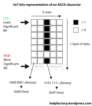
Every character in this code example is displayed in an 5×7 matrix. This means that every hex-value (byte) of data represents one row in this matrix. As you can see the first and last two bytes of the explanation mark data is empty/null so that only the row in the middle is filled. As you remember we set the display controller to draw the data horizontally that means that every byte of data is saved row after row. If the controller reaches the 84th byte of data it jumps to the next column. Have a closer look at point 7.7 of the PDC8544 datasheet to undertand this fact.

Have a look at this picture to understand the 5×7 pattern.

Describing image of the representation of an ASCII character with a grid of 5x7 bits

As you can see the eighth bit of data is not part of the actual character. It is used to create a margin at the bottom of the symbol.
The data is written into the controllers memory by using the LcdWrite() method.

void LcdWrite(byte dc, byte data) {
  digitalWrite(PIN_DC, dc); //Data or Command?
  digitalWrite(PIN_SCE, LOW); //Enable chip
  shiftOut(PIN_SDIN, PIN_SCLK, MSBFIRST, data); //Shift data bit by bit, most significant bit first
  digitalWrite(PIN_SCE, HIGH); //Disable chip
}

The first parameter defines whether  the passed data is a command for the controller or just data to be written into the memory (like a single character). After the DC pin is set to HIGH or LOW and the chip is enabled to receive data, the actual data transfer starts. The data is shifted bit by bit into the memory of the controller starting with the most significant bit (MSB). That means the the first bit (from left) is put into the memory first. This pixel will be passed bit after bit into the last column of the 5×7 matrix. Have a look at the above picture to understand that fact.

The method LcdCharacter() does exactly the same for every byte (row of data) for an defined ASCII character of the already mentioned array.

void LcdCharacter(char character) {
  LcdWrite(LCD_D, 0x00); //Writes empty row
  for (int index = 0; index < 5; index++) {
    LcdWrite(LCD_D, ASCII[character - 0x20][index]); //Finds the passed character in the ASCII array and writes it row by row (byte by byte)
  }
  LcdWrite(LCD_D, 0x00); //Writes empty row
}

That’s all. I hope I could help to set your Nokia 5110 display up and run it with your Arduino.

Standard
Anleitungen, Arduino

[Arduino] Connecting a Nokia 5110 display to Arduino – Part2: Explaining the code library

In this second part of the Nokia 5110 display tutorial I will explain the code library from the Arduino website. I’ve chosen the second example written by Jim Park. The main topic of this post is the initialization of the display by code. The presentation of a character will be treated in the third and last chapter of this tutorial.

Lets start with the definitions:

 #define PIN_SCE 12
 #define PIN_RESET 10
 #define PIN_DC 9
 #define PIN_SDIN 11
 #define PIN_SCLK 13
 #define PIN_LED 6
 #define LCD_C LOW //Send command
 #define LCD_D HIGH //Send data
 #define LCD_X 84
 #define LCD_Y 48

The first part describes the wiring, which I explained in the last tutorial. Then there are two constants set called LCD_C and LCD_D. The first one is used to send a LOW to the controllers D/C port. This LOW indicates that the following eight bits represent a command that has to be interpreted by the controller. Sending a HIGH to the controller indicates that the following byte of data shall be written into the memory of the controller and finally be shown on the display.

The last two constants define the width (LCD_X) and height (LCD_Y) of the display measured in pixels.

After that a long constant array of ASCII character has been defined. As already mentioned this part will be explained in the next chapter. So let’s take a look on the setup()-method now.

void setup(void) {
 LcdInitialise();
 LcdClear();
}

So this one looks quite easy. We are just calling two methods. The first one is LcdInitialise():

void LcdInitialise(void) {
 pinMode(PIN_SCE, OUTPUT);
 pinMode(PIN_RESET, OUTPUT);
 pinMode(PIN_DC, OUTPUT);
 pinMode(PIN_SDIN, OUTPUT);
 pinMode(PIN_SCLK, OUTPUT);
 pinMode(PIN_LED, OUTPUT);
 //Needed to initialize the display. Without reset display might get damageed
 digitalWrite(PIN_RESET, LOW);
 digitalWrite(PIN_RESET, HIGH);
 LcdWrite(LCD_C, 0x21 ); // LCD Extended Commands.
 LcdWrite(LCD_C, 0xB1 ); // Set LCD Vop (Contrast). //B1
 LcdWrite(LCD_C, 0x04 ); // Set Temp coefficent. //0x04
 LcdWrite(LCD_C, 0x13 ); // LCD bias mode 1:48. //0x13
 LcdWrite(LCD_C, 0x0c ); // LCD in normal mode. 0x0d for inverse
 LcdWrite(LCD_C, 0x20); // Set chip active, user basic instructions, use horizontal adressing
 LcdWrite(LCD_C, 0x0C); //No Operation
 digitalWrite(PIN_LED, HIGH); //Enables the backlight of the display
}

In the first part of the method the ports on the Arduino are set to output-mode. The next part performs a reset of the displays memory by giving the display a LOW followed by a HIGH. As the comment says this is needed (because the datasheet says so in chapter 8.1) otherwise the display might get damaged.

The next lines contain some commands represented by a hex value. Let’s have a look on the following line:

LcdWrite(LCD_C, 0x20);

The value of LCD_C is a LOW. The value 0x20 is represented binary as 0010 0000. So we have an binary 1 on the third bit. If you now take a look at  Table 1 on page 14  of the datasheet you see the following table:

Example of an instruction for the PCD8544 controller

The first rows shows the state of the D/C port and the other eight rows describe the value of the data bits. As you can see the command “Function set” has an 1 on the third position. The first three (least significant bits) are named PD, V and H. This values are described in table 2 on the same page.

Description of the Function Set command of the PCD8544

So with the value 0010 0000 and the D/C port on LOW we are setting

  • the PD value to 0, which means the chip is active
  • the V value to 0, which enables the horizontal addressing
  • and the H value to 0, which enables the basic instruction set

Sending a 0010 0010 (0x22) command for example would enable the vertical addressing.

The last call in the setup()-method is the LCDClear() command:

void LcdClear(void) {
 for (int index = 0; index < LCD_X * LCD_Y / 8; index++) {
    LcdWrite(LCD_D, 0x00);
 }
}

The LCDClear() method loops through the whole memory and sets it to 0 with the effect that the displays gets blank.  The PDC8544 expects always a set of eight bit (one byte) of data at once. So the number of pixels (LCD_X*LCD_Y) has to be divided by eight to get the correct number of memory slots to fill. Each of this slots saves one byte of data which is filled with 0x00 or 0000 0000.

Using this code your display will be (hopefully) initialized correctly but should remain without any content. In the next part we will fill it with some text.

Standard
Anleitungen, Arduino

[Arduino] Connecting a Nokia 5110 display to Arduino – Part1: Wiring

If you own an Arduino you surely start (sooner or later) playing around with some kind of display. Maybe dot matrix displays, classical 16×2 lcds or like me an old Nokia 5110 lcd with a resolution of 84×48 pixels.

The first problem you come across is wiring the whole thing up. Like everyone else nowadays you start to google and with a chance of 99.99% you discover this great library for the Philipps PCD8544 controlled screen on the official Arduino website. This code is a very nice piece of work, but for people like me, who have very low experience with electronic devices, it is very hard to understand. Coming across a lot of websites and boards I noticed that many people have issues setting the Nokia 5110 lcd up. This fact was  responsible for writing this blog post.

Wiring

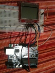
Let’s start wiring up the display to the Arduino. In my case the lcd came mounted on an PCB with eight header pins which can be easily connected to a common breadboard. The materials you need for assembling this project are the following

  • Arduino (or Arduino-compatible board)
  • Breadboard
  • Nokia 5110 display
  • Jumper wires
  • Current limiting resistor with at least 180 Ohm (if you want to use the displays backlight)

A link on the website of the displays retailer referred to a datasheet. Well, more precisely said it linked to the displays controller datasheet. For me as an non-professional it looked very disturbing. So after long studying and wondering where to start I analyzed the sample code on the Arduino website.

#define PIN_SCE   7  // LCD CS  .... Pin 3
#define PIN_RESET 6  // LCD RST .... Pin 1
#define PIN_DC    5  // LCD Dat/Com. Pin 5
#define PIN_SDIN  4  // LCD SPIDat . Pin 6
#define PIN_SCLK  3  // LCD SPIClk . Pin 4
                     // LCD Gnd .... Pin 2
                     // LCD Vcc .... Pin 8
                     // LCD Vlcd ... Pin 7

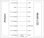
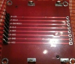
Comparing the mentioned connectors with the named ones on my PCB I came across the problem that the SPIDat (the serial input connection) was not present on my board. Instead there was a pin named DN-MOSI which is just another name for the serial-in port. In the example above there are also three pin connections that are not assigned to a pin number on the Arduino because there are two possibilites to wire them up. A look in the datasheet shows that the controller is running with an Vcc of 3,3V. So the options are to connect the display to the 3,3V anlog pin or to a PWM-capable digital port with reduced voltage.

The connection of the backlit can be solved by using a 5V pin in combination with a current limiting resistor. It is up to you which port you use. Choosing an PWM-capable port  has the advantage of adjusting the displays brightness simply by code. Connecting the GND should be clear. My final connection looks like this.

And here the code:

#define PIN_SCE 12
#define PIN_RESET 10
#define PIN_DC 9
#define PIN_SDIN 11
#define PIN_SCLK 13
#define PIN_LED 6

In the next part I will give you a detailed explanation of the 5110 LCD Library.

Standard
Anleitungen

Doppelte Geburtstage in iCal dank iCloud

Ich nutze meinen iCloud Account auf insgesamt fünf Geräten. Gestern fiel mir zum ersten Mal auf, dass Einträge aus dem Geburtstagskalender doppelt angezeigt werden. Scheinbar ist beim Synchronisieren irgendwo etwas schief gelaufen. Die Lösung war allerdings sehr simpel:

  1. Öffnet die Einstellungen für iCloud (in den Systemeinstellungen)
  2. Entfernt das Häkchen vor dem Adressbuch
  3. Drückt nun auf “Vom Mac löschen”
  4. Setzt das Häkchen vor dem Adressbuch wieder
  5. Wählt “Zusammenführen”
Delete Contacts from iCloud Screenshot

Delete Contacts from iCloud Screenshot

Die doppelten iCal Geburtstagseinträge sollten nun verschwunden sein.
Standard
Iphone, Tips

This device isn’t eligible for the requested build.

Itunes quittierte den Versuch die Firmware meines Iphones zu updaten mit folgendem Fehler:

This device isn’t eligible for the requested build.

Die Lösung war nicht zu ergooglen und doch ganz simpel. Solltet ihr euer Iphone in der Vergangenheit mal gejailbreakt haben, so könnte sich in der /etc/hosts noch ein Eintrag befinden, der die Kommunikation an den Verifizierungsserver von Apple untersagt. Löscht also den Eintrag für den Host gs.apple.com aus der Datei und alles ist in Butter.

Standard
Anleitungen, Mac, Software

[MAC] wunderlist startet nicht – Fatal Error

In vielen Blogs wurde das GTD-Tool wunderlist hoch angepriesen. Da ich eine kostenlose App gesucht habe, mit der ich die Tasks auf dem Iphone sowie dem Mac synchronisieren konnte, wurde ich darauf aufmerksam.

Beim ersten Starten kam dann die Ernüchterung in Form folgender Fehlermeldung:

wunderlist appears to have encountered a fatal error and cannot continue
The application has collected information about the error in the form of detailed error report.

Screenshot des fatal errors der wunderlist

Im besagten error report (/Library/Application Support/Titanium/appdata/tiapp.log) findet sich dieser dubiose Fehler:

[10:18:17:726] [Titanium.Proxy] [Error] Failed PAC request: The operation couldn’t be completed. (kCFErrorDomainCFNetwork error 2.)

Logeintrag der wunderlist nach dem fatal error

Nach langem Suchen und viel Rumprobieren habe ich die Ursache gefunden. Die Fehler werden durch die Proxy-Konfiguration von OSX ausgelöst. Hier der Workaround:

  1. Öffnet die Systemeinstellungen
  2. Klickt auf Netzwerk
  3. Drückt auf die Schaltfläche “Weitere Optionen”
  4. Wählt nun den Reiter “Proxies”
  5. Deaktiviert die Option “Automatische Proxy-Entdeckung”
  6. Speichert mit einem Klick auf “OK”

Deaktivieren der automatischen Proxy-Entdeckung

Sollte sich in eurem Netzwerk ein Proxy-Server befinden, so müsst ihr diesen natürlich manuell eintragen. Viel Erfolg.

Standard
Anleitungen, Iphone

Iphone 3GS (altes Bootrom) IOS 4 Jailbreak – Mein Vorgehen auf dem Mac

Zunächst möchte ich klarstellen, dass dieser Beitrag nicht als Schritt-für-Schritt-Anleitung zu verstehen ist, sondern eher als eine Wiedergabe meines Vorgehens. Bedingt durch die komplexe Thematik des Iphone-Jailbreaks (verschiedene Modelle, verschiedene Firmware-Versionen, verschiedene Bootroms) weiss ich nämlich gar nicht, ob mein Vorgehen “optimal” ist.

Schaut man sich allerdings die unzähligen Foren und Blogs zu diesem Thema an, so überkommt einen das Gefühl, dass es Niemand mehr so genau weiss. Hin und wieder führt mein Beitrag in eine Sackgasse, die sich sicherlich auch umgehen lässt. Entscheidend ist aber, dass die ganze Aktion von ERFOLG gekrönt war.

Die Ausgangssituation

Weil ich natürlich ein Opfer unserer schnelllebigen Gesellschaft bin, und Geduld eine Tugend ist, die ich lediglich beim Aufschieben von lästigen Arbeiten an den Tag lege, habe ich natürlich direkt beim Release des IOS 4 auf die neuste Version upgedated. Kurz darauf musste ich dann erstaunt feststellen, dass Itunes sich strikt weigert meine Custom-Firmware, die ich mit dem pwnage-Tool erstellt habe, zu installieren.

Ein zweiter Blick auf die Dev-Team Seite verrät mir, dass ein Jailbreak für mich erstmal nicht verfügbar war.
Warum? Ich habe (mal wieder aus Bequemlichkeit) den Jailbreak der Version 3.1.3  mit dem Spirit Jailbreak durchgeführt, und natürlich wird exakt dieser Jailbreak nicht vom pwnage-Tool unterstützt.

Das Ziel

Ein gejailbreaktes IOS 4 .0 auf dem Iphone 3GS, das zuvor mit Spirit geöffnet wurde.

Die Anforderungen

Natürlich müssen, wie eigentlich in jeder Jailbreak-Anleitung, einige Anforderungen erfüllt sein.

  • Ihr besitzt ein Iphone 3GS mit altem Bootrom. Hier eine schöne Anleitung, wie man herausfinden kann, welche Version euer Handy besitzt.
  • Ich gehe mal davon aus, dass ihr auch schon auf IOS 4 seid.
  • Euer Jailbreak der Firmware 3.1.3 verlief mit Spirit
  • Ihr habt bereits einen 3.1.2 Jailbreak durchgeführt, beispielsweise mit Blackra1n
  • Itunes in der Version 9.2.x
  • Ihr solltet der englischen Sprache mächtig sein, da ich selbst auf einige Anleitungen nur verweise

Die Tools

Ich bin Mac-User und nutze daher natürlich auch die entsprechenden Mac-Tools. Die aufgelisteten Software-Pakete gibt es, ausgenommen des pwnage-Tools, alle auch für die Microsoft-Systeme. Da unter Windows ein Jailbreak namens Snowbreeze verfügbar ist, müsste das Vorgehen daher analog zu meiner Anleitung auch mit Snowbreeze funktionieren.

Wir benötigen folgende Pakete:

Schritt 1 – Downgrade auf Version 3.1.3

Das Dev-Team erwartet beim aktuellen Jailbreak ein Gerät, dass zuvor NICHT mit Spirit gejailbreakt wurde. Also war mein erster Gedanke diesen Zustand wiederherzustellen. Stichwort: Downgrade von 4.0 auf 3.1.3.

Da Steve Jobs-Gefolgsmannen dem gewöhnlichen Jailbreaker aber immer mehr Steine in den Weg legen, ist ein Downgrade auf dem 3GS mal wieder nicht einfach ein simpler Klick. Stattdessen muss man Itunes verbieten nach Hause zu telefonieren. Der Trick ist die Bearbeitung der hosts-Datei eures Betriebsystems. Statt zum Apple-Server leitet ihr die Anfrage durch Itunes an Sauriks Server (der Cydia-Typ), der Itunes dann bestätigt, dass die Firmware-Version 3.1.3 auf diesem Telefon installiert werden darf. Da euer 3GS ja bereits gejailbreakt ist, stellt dies kein weiteres Problem dar.

Ich will das Rad an dieser Stelle nicht neu erfinden und verweise einfach auf folgende Anleitung, die zeigt, wie ihr die hosts-Datei bearbeiten müsst, um Itunes (sagen wir es einfach mal laut) zu verarschen. Hier ist der Punkt “Bypassing the Overlord” der Entscheidende.

Nun geht es ans Eingemachte. Sichert zunächst die Daten eures Mobiltelefons mittels iTunes-Sync. Jetzt geht es darum das Telefon in den DFU-Mode zu bringen. Und weil mir bei meiner endlosen Recherche aufgefallen ist, dass 50% der Jailbreaker den Unterschied zwischen DFU- und Recovery-Mode nicht kennen, verweise ich ebenfalls auf diese Anleitung. Führt gemäß dieser bitte die Schritte durch, die euer Smartphone in den DFU-Mode bringen.

Meldet iTunes nun ein neues Gerät im Wartungsmodus, klickt ihr mit gedrückter Auswahltaste auf Wiederherstellen und wählt die heruntergeladene Firmware-Version 3.1.3 aus.

Ist die Installation abgeschlossen hängt euer Handy im Recovery-Modus fest. Startet Recboot und beendet den Modus mittels Klick auf “Exit Recovery Mode”.
Wenn Alles geklappt hat, dann habt ihr nun eine saubere Firmware-Version 3.1.3.

Schritt 2 – Jailbreak der Version 3.1.3

Der nächste logische Schritt wäre der Jailbreak der Version 3.1.3. Dazu gibt es das pwnage-Tool in der Version 3.1.5. Schnell die Custom-Firmware erstellt, Iphone nochmal in den DFU-Mode geworfen und mittels Itunes aufgespielt. Und siehe da: Fehler 160x.

Ich habe es mit diversen Itunes-Versionen und Custom-Firmwares probiert: Nichts hat funktioniert. Fehler 1600, 1601, 1604. In diversen Foren wird die Verwendung von iREB vorgeschlagen. Ich habe es erst gar nicht ausprobiert, denn iREB unterstützt laut Entwickler das 3GS nicht. Ich wiederhole es noch einmal: IREB UNTERSTÜTZT DAS 3GS NICHT!!!

Aus Verzweiflung blieb mir nichts anderes übrig als weiter zu Downgraden auf Version 3.1.2. Das meinte ich mit “Sackgassen”.

Schritt 2 –  Downgrade auf Version 3.1.2

Es wäre natürlich zu schön gewesen, wenn man einfach auf Version 3.1.2 downgraden könnte. Aber nein, wir benötigen eine alte Itunes-Version, die Version 9.1.1, um genauer zu sein. Als Mac-User steht man da leider erstmal wieder vor einer großen Hürde. Denn ein Itunes Downgrade ist nicht einfach. Auch hier möchte ich das Rad nicht neu erfinden und zeige daher auf diese fertige Anleitung: Downgrade iTunes 9.2 to 9.1.1

Ich persönlich habe mich da drum rum gemogelt, indem ich iTunes in der Version 9.1.1 (Downloadlink oben)  auf meiner Bootcamp-Partition installiert habe. Natürlich müsst ihr hier noch einmal vorher die /etc/hosts-Datei bearbeiten.

Habt ihr nun ein funktionsfähiges iTunes in der Version 9.1.1, so könnt Ihr euer iPhone noch einmal in den DFU-Mode versetzen und mit gedrückter Auswahltaste und einem Klick auf “Wiederherstellen” die Firmware-Version 3.1.2 installieren. Am Ende des Vorgangs gibt es eine Fehlermeldung, da es mit dieser Version eigentlich ein Baseband-Update gäbe. Dies ist aber nicht weiter schlimm. Ignoriert einfach den Fehler. Solltet ihr nun wieder im Recovery-Mode festhängen, so müsst ihr noch einmal RecBoot starten und den Recovery-Mode beenden.

Ihr seid nun auf Version 3.1.2 und könnt euch wieder dem Jailbreak-Train anschließen.

Schritt 3 – Jailbreak mit Blackrain

Ausnahmsweise mal ein einfacher Schritt. Startet Blackrain, klickt auf “make it ra1n” und wartet ab. Nach einem Neustart ist euer Smartphone auf 3.1.2 und gejailbreakt.

Schritt 4 – IOS 4 installieren

Erstellt nun mit dem pwnage-Tool 4.0.1 die Custom-Firmware des IOS 4.0. Sollte das pwnage-Tool fragen, ob ihr bereits gejailbreakt habt, dann antwortet einfach mit JA. Solltet ihr Itunes im Schritt zuvor downgegradet haben, so geht es jetzt wieder ans Updaten. Um die neuste Firmware-Version zu installieren, braucht ihr ebenfalls die neuste Itunes Version.

Ist Itunes auf dem neusten Stand, könnt ihr nun wieder mit Hilfe des Wiederherstellens-Button eure Custom-Firmware auswählen und installieren. Nach ca. 10 Minuten habt ihr ein gejailbreaktes Iphone 3GS mit altem Bootrom in der IOS Version 4.0.

Schlussbemerkung

Ich persönlich werde nicht noch einmal den Fehler machen auf irgendwelche anderen Jailbreak-Tools zu wechseln. Das Rumgehampel mit den Custom-Firmware scheint zwar nervig, aber es ist zukunftsfähig. Beim Jailbreak sollte Bequemlichkeit kein Thema sein. Genau so wichtig ist es sich in Geduld zu üben. Ein Update zur falschen Zeit und eine Menge Stress kommt auf euch zu.

Ich hoffe ich konnte euch ein paar Ansätze geben mit dem Thema IOS 4 Jailbreak auf dem 3GS umzugehen.

Standard